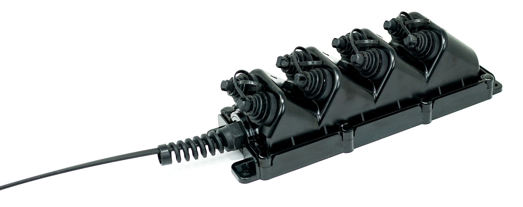
- Port Count: 2, 4, 6, 8, or 12 ports
- Splitter Configurations: 1×2, 1×4, 1×6, 1×8, or 1×12 PLC splitters
- Fiber Type: Single-mode (OS2)
- Cable Type: Available in Toneable or Dielectric options
- Termination: OptiTap®-style single-fiber connectors for customer drop terminations
- Cable Lengths: Standard lengths range from 50 ft to 2,500 ft, with customization available based on deployment needs
- Design: Pre-terminated with splitter tails for simplified network deployment
- ROHS/REACH compliant
MST – Splitter Tail
Product Overview
NetSource’s MST Fiber Terminals with Splitter Tails, designed and manufactured in the U.S., provide a durable and efficient solution for fiber-to-the-x (FTTx) network deployments. Engineered to withstand harsh outdoor conditions, these IP68-rated terminals ensure long-term reliability with robust protection against dust and water ingress. Each terminal is preconfigured with factory-installed splitters and terminated with OptiTap®-style single-fiber connectors, simplifying drop installations and reducing field labor.
By integrating splitter tails, these MSTs eliminate the need for separate splitter enclosures, reducing installation complexity and field splicing. This design enables incremental network expansion, making it an ideal solution for both rural broadband and high-density deployments. By efficiently distributing fiber, it helps
Available in 2-port (1×2 splitter), 4-port (1×4 splitter), 6-port (1×6 splitter), 8-port (1×8 splitter), and 12-port (1×12 splitter) configurations, these MSTs optimize fiber utilization by reducing the number of feeder fibers needed. This results in lower capital expenditures and faster customer activation, supporting scalable and cost-effective FTTx network expansion.
- Product Specifications
- Environmental and Mechanical Properties
- Features and Benefits
- Conformance Standards
- Downloads
- Operating Temperature: -40°C to 70°C (-40°F to 158°F)
- Cold Mate/Demate Performance: Tested to -40°C (-40°F) without significant insertion loss
- Ingress Protection: IP68 — OptiTap® Interface
- Integrated PLC splitter reduces distribution fiber requirements, allowing a single feeder fiber to serve multiple subscriber drops
- Factory-integrated hardened connections provide reliable environmental protection for demanding outside plant deployments
- Plug-and-play drop ports simplify subscriber connections, reducing field splicing and installation time
- Integrated splitter and distribution terminal in one enclosure eliminates the need for a separate splitter enclosure and simplifies network architecture
- Multiple splitter and port configurations provide deployment flexibility for a range of FTTH and FTTx network designs
- Versatile OSP design supports aerial, pole, pedestal, handhole, and below-grade installations, providing a common terminal solution across multiple deployment environments
- Optical Performance:
- FOTP-171 (TIA/EIA-455-171) – Insertion Loss
- FOTP-107 (TIA/EIA-455-107) – Return Loss
- Endface Geometry & Inspection:
- IEC 61300-3-35 – Visual Inspection
- IEC 61755-3-1 – Endface Geometry — Single-Fiber
- Environmental/Mechanical (Connectors & Assemblies):
- GR-3120 – Environmental, Mechanical & Performance Requirements
- GR-771 – Outdoor Terminal / Closure Environmental & Mechanical Requirements
- Outdoor Cable Requirements:
- GR-20 – Outside Plant Cable Environmental & Mechanical Requirements
Part Number Chart
| HE | – | PLC Splitter | P | Cable Type | Cable Construction | Connector | – | Length | Unit |
| 1×4 | SM: Singlemode OS2 | D1: Dielectric | 57: Hardened SC/APC | XXX | FT | ||||
| 1×6 | D3: Toneable | XXX | M | ||||||
| 1×8 | |||||||||
| 1×12 |
Notes : add R for reverse Pull (Pull from the Terminal end) Lengths over 950ft on a reel
Dimensions
| Port Configuration | H (in/mm) | L (in/mm) | W (in/mm) |
| 2/4 Port | 3.65 / 92.71 | 8.25 / 209.80 | 4.38 / 111.25 |
| 6 Port | 3.65 / 92.71 | 10.50 / 266.70 | 4.38 / 111.25 |
| 8 Port | 3.65 / 92.71 | 13.25 / 336.55 | 4.38 / 111.25 |
| 12 Port | 4.25 / 107.95 | 14.25 / 361.95 | 5.32 / 135.13 |
Insertion Loss Chart
| Parameter | 1×4 | 1×8 |
| Working Wavelength (nm) | 1260-1650 | |
| Fiber Type | G657A1 or Customized | |
| Insertion Loss (dB) | 7.1 | 10.2 |
| Uniformity (dB) | ≤0.5 | ≤0.8 |
| Polarization Dependent Loss (dB) | ≤0.25 | ≤0.25 |
| Return Loss (dB) | ≥55 | |
| Directionality (dB) | ≥55 | |
| Fiber Length (dB) | 1.0 or Customized | |
| Temperature Stability (dB) | -40°C to 85°C (≤0.5) | |
| Working Temperature | -40°C to 85°C | |
| Storage Temperature | -40°C to 85°C | |
| Maximum Power (mW) | 300 | |