The size of an MDC® connector is one of its biggest advantages in the field. In manufacturing, that compact footprint also raises the importance of process control.
MDC cable assemblies are designed for environments where fiber density matters. US Conec developed the MDC platform around two 1.25 mm ferrules in a very small form factor, allowing three MDC adapter ports to fit into the panel space traditionally occupied by a duplex LC adapter. That can provide up to three times the fiber density of LC within the same footprint.
NetSource is expanding its custom fiber manufacturing capabilities to include assemblies built around the MDC® connector platform. MDC® is a registered trademark of US Conec. For customers evaluating the technology, connector density is only part of the story. It also matters how the assembly is terminated, polished, inspected, configured, and tested before it ever reaches the network.
This article looks inside that manufacturing process and explains why those steps matter when evaluating an MDC cable assembly and the value it can deliver.
An MDC Cable Assembly Is More Than a Smaller LC
The MDC platform borrows something familiar from the LC ecosystem: the 1.25 mm ferrule.
But the surrounding connector design is different. MDC places two ferrules into a much smaller housing and uses US Conec’s DirectConec™ push-pull boot, allowing technicians to insert and remove individual connectors in crowded panels. The connector is available for multimode, single-mode, and single-mode APC applications, and US Conec specifies support for cables up to 2.0 mm in diameter.
For a network designer, those details translate into density and accessibility.
For a cable assembly manufacturer, they translate into manufacturing requirements.
Fiber preparation, termination, polishing, inspection, polarity management, and optical testing must work together. A smaller connector does not eliminate any of those steps. If anything, high-density applications make consistency more important because the finished assemblies will often be deployed in environments where serviceability and space are already at a premium.
For the buyer, the practical question is not simply whether a manufacturer can put an MDC connector on a cable. It is about whether the finished assembly has been built and verified consistently enough to perform as expected once it is installed.
Preparation and Termination Set the Foundation
Every fiber assembly begins well before final optical testing.
Cable and fiber have to be prepared correctly for the connector being installed. Components must be assembled according to the connector system’s process, and the fiber has to be positioned and terminated consistently before polishing can produce the intended end face.
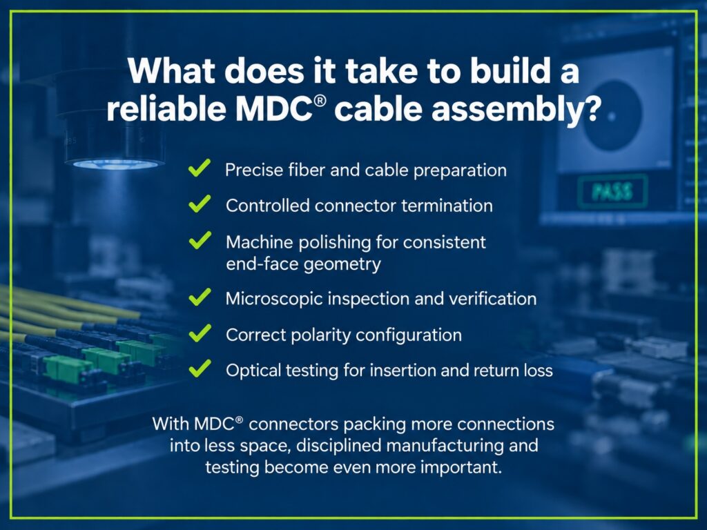
US Conec maintains dedicated MDC termination and assembly training rather than treating MDC as a simple variation of another duplex connector. Its published curriculum includes cable and fiber preparation, connector termination, machine polishing, inspection, polarity configuration, and optical testing.
That is worth paying attention to.
When organizations evaluate a new connector platform, the connector specification is only part of the decision. The manufacturing ecosystem behind it matters too. Reliable deployment depends on manufacturers being able to reproduce the assembly correctly, not just purchase the components.
Polishing Is an Optical Process
Connector polishing can sound like a finishing step. In fiber manufacturing, it directly affects optical performance.
The goal is to create ferrule end faces with the geometry and surface quality required for proper fiber-to-fiber contact. Problems introduced during polishing can manifest later as excessive insertion loss, poor return loss, or unreliable mating performance.
US Conec’s MDC training addresses machine polishing along with microscopic visual inspection of polished ferrules. The curriculum also includes interferometric examination of ferrule end-face geometry and measurement of the geometry of the 1.25 mm ferrules used by the platform.
For the customer, none of this work is visible when an assembly arrives.
That is precisely the point.
A finished cable assembly should be ready to be integrated into the network without requiring the installer to think about what happened on the production floor. The manufacturing controls behind the assembly are what make that possible and help protect installation outcomes.

Inspection Matters Before the Assembly Leaves Manufacturing
Fiber end faces are sensitive to contamination and physical defects. In high-density connectivity, inspection and cleaning become especially important because multiple connectors are packed into a smaller working area.
US Conec offers the IBC™ Cleaner MDC specifically for this interface. Although MDC uses familiar 1.25 mm ferrules, standard LC cleaners cannot reach MDC connectors behind the adapter because of the smaller port opening and tighter spacing between connectors. The MDC-specific cleaner is designed to reach those connections without disturbing adjacent connectors.
The manufacturing side follows the same basic principle: inspect before relying on the connection.
Microscopic examination helps identify defects or contamination that could affect optical performance. End-face geometry can also be evaluated before the assembly moves forward.
The practical takeaway is simple. Density does not reduce the need for inspection. It makes disciplined inspection more valuable.
Polarity Has to Be Right Too
Optical performance is only one part of a usable duplex assembly.
Transmit and receive paths still need to arrive where the network expects them.
The MDC platform includes polarity configurability, and US Conec designed the connector so polarity can be reversed without exposing or twisting the fibers. Its manufacturer training includes both polarity-management instruction and hands-on connector configuration.
That flexibility is useful, but it also means polarity needs to be treated as a defined assembly requirement.
For custom cable assemblies, manufacturers need to understand how a cable will be deployed and build the assembly around the intended application rather than treating connector selection as an isolated specification.
This is also where working with a manufacturer that understands the larger fiber architecture becomes valuable. The right question is not only, “Do you need MDC?” It is also, “How does this assembly need to interact with the rest of the system?”
Optical Testing Closes the Loop
Visual inspection can tell a manufacturer a great deal about a connector. It cannot replace optical testing.
US Conec’s MDC training includes insertion-loss and return-loss testing, along with instruction on the optical test equipment used to evaluate finished connectors. Its training program also provides for follow-up evaluation of customer-produced products, including insertion-loss testing and end-face examination.
That gives the manufacturing process a useful final checkpoint for buyer confidence.
Did the assembly come together correctly?
Does it perform optically the way it is supposed to?
For a customer comparing assembly providers, those questions matter more than the connector specification by itself. Higher density creates value only when the finished connectivity can be reliably manufactured and verified for use.
Why the Manufacturing Ecosystem Matters to MDC Adoption
A new connector platform has to solve more than an engineering problem on paper.
Network owners need components. Assembly manufacturers need repeatable termination processes. Technicians need workable installation and cleaning procedures. Test equipment has to support the interface. Engineers need confidence that the platform can be introduced without creating unnecessary operational risk.
US Conec has built training, process documentation, tools, inspection procedures, and testing support around the MDC platform as part of that ecosystem.
That helps explain why the conversation around MDC is broader than connector density alone.
Three times the LC density is an important specification. Being able to consistently manufacture, inspect, test, install, clean, and maintain those connections turns the specification into usable network infrastructure.

Where NetSource Fits
NetSource is expanding its custom fiber manufacturing capabilities to include MDC-based cable assemblies as customers evaluate higher-density connectivity for data centers and other fiber-intensive environments.
That work fits naturally into the broader role NetSource already plays with its customers.
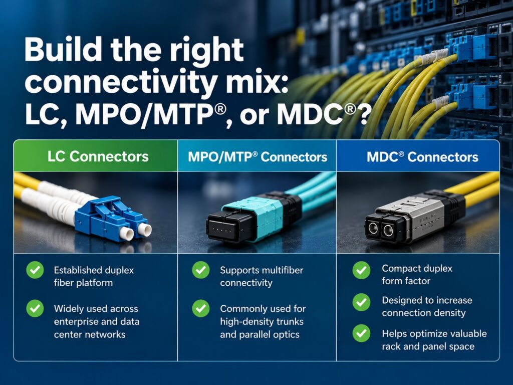
Connector selection is rarely an isolated decision. It can affect panel density, cable design, polarity, migration planning, existing LC or MPO/MTP® infrastructure, and the way future capacity is added. So each choice should support the broader deployment plan.
NetSource works with customers on those broader questions, including custom assembly design, application requirements, infrastructure planning, and selecting the connectivity approach that makes sense for a particular deployment.
For organizations considering MDC cable assemblies, the conversation can start with density. It should not end there.
The better question is whether MDC fits the architecture being built, how it should integrate with the existing infrastructure, and how the assemblies themselves will be manufactured and verified before they reach the network.
If your organization is evaluating MDC cable assemblies or determining how MDC should fit alongside existing LC or MPO/MTP® infrastructure, contact NetSource to discuss the application. The team can help with custom assembly design, connector selection, polarity requirements, migration planning, and broader connectivity decisions for deployment.